Here is the list of our top 5 arduino simulators.
Virtual Breadboard for Arduino

Launched in 2005, the Arduino open hardware and software platform has grown to be very popular among hobbyists, educators, and professionals alike, gaining momentum especially in the robotics field. Backed by a massive online community, and with most development boards and hardware accessories available at very low prices, this platform is perhaps the best place to start in working with embedded devices. But what if you want to learn programming and do not own an Arduino board, or are overwhelmed by the selection of hardware out there? This is where simulation software comes in.
Virtual Breadboard for Arduino is a learning App designed to help you take the first steps in the exciting world of physical computing with the Arduino microcontroller and ‘Breadboard’ based electronic circuit models.
Virtual Breadboard for Arduino is a learning App designed to help you take the first steps in the exciting world of physical computing with the Arduino microcontroller and ‘Breadboard’ based electronic circuit models.
With VBB4Arduino you will
- Learn from 75 built in Arduino examples
- Explore dozens of different types of sensors, motors and lights
- Learn the Arduino commands and what they do
- Edit your own code examples
Simulator for Arduino by Virtronics
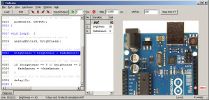
Simulator for Arduino is the most full featured Arduino Simulator available at the present time
The benefits and features of the Arduino Simulator are:
- The ability to teach and demonstrate the inner workings of an Arduino sketch
- Test out a sketch without the hardware, or prior to purchasing hardware
- Debug a sketch
- Demonstrate a project to a potential customer
- Develop a complicated sketch faster than using the hardware
Download the free version below with a short delay timer on loading a sketch, and when ready upgrade to the Pro Version. Simulator for Arduino Pro Version is currently used in many countries over six continents. The download consists of a zip file containing a setup.exe file which installs an exe file, help files, images and examples. It is designed for the Arduino Uno, Mega and most other common Arduino boards and does the following:
- Steps through the program line by line. If a new line is selected, the program will continue from that point.
- Performs digitalWrite, digitalRead and PinMode for pins 0-53
- analogRead for pins 0-16 and analogWrite for digital pins 0-53
- Emulates Serial, LCD output, Ethernet, Servo, SD card, EEPROM, SoftSerial,SPI, Wire
- If,while,for,switch, do whileloop functionality
- Subroutines (multi-level) with arguments
- View variables in real-time
- Step Into, Step Over, Step Out of or Run mode
- Ability to edit sketch or open in Arduino IDE
- Tabs for separate files in the sketch
- Context-sensitive help
- 2 and 4 line LCD support only with improvised CGRAM
- 2 dimensional arrays (without initialisation)
- BreakPoint now with a conditional option
- load custom libraries automatically after setting the Library Directory
- Change the font, size and style of the Simulator
- Advanced watch for easy variable viewing
- Minimize mode for demo/training
- Limited support for custom libraries
- Limited support for pointer and structures
Limitations :
- Pointers not implemented – some sketches with pointers may run but generally pointers don’t work
- Custom Libraries, structures,classes and enums may or may not work
- Other minor issues to do with complicated C++ commands
- Firmata needs work
- Mouse object will run but not yet implemented
- typdef function pointers not implemented
- MAC,iOS interface not implemented
- simple typdefs work but typedef with enum or structs to be implemented
CodeBlocks Arduino IDE with Simulator

CodeBlocks Arduino IDE is a customized distribution of the open-source Code::Blocks IDE enhanced for Arduino development. It provides more demanding software developers with everything a modern IDE should have including code foldering, code completion, code navgiation, compiling as well as uploading for Arduino. With a dedicated project wizard, it’s easy create a ready-to-go Arduino project. The distribution integrates latest Arduino core files, standard Arduino libraries, AVR toolchain, Arduino Builder, a serial terminal and most interesting, an API-level Arduino simulator (under development).
Code block ide with simulator Features:
Code block ide with simulator Features:
- dedicated project wizard for Arduino development
- integrated Arduino core files and libraries
- compiled core files cached for faster compiling speed (comparing to original Arduino IDE)
- integrated pre-configured AVR compiler toolchain
- popular Arduino boards supported as build targets
- uploading HEX to Arduino boards (Leonardo supported) by running the built target
- Arduino API-level simulator (very early stage) integrated (as a build target)
Simuino Arduino Simulator

Simuino is an Arduino UNO/MEGA Pin Simulator.
You can download the terminal version (latest version is v0.1.9) at www.simuino.com. NOTE: Downloads available on code.google.com is not the latest!
Run your sketch and evaluate in/out status of the digital and analog pins. The GUI is based on ncurses, i.e. run Simuino from a terminal window. Features animation in realtime according to actual delays in sketch.
The perfect tool for anybody who wants to get started with Arduino Sketch construction.
It is also possible to construct scenarios regarding analogRead, digitalRead and External Interrupts.
The purpose is to make the construction of a sketch easier. You can verify the functionality without having the Arduino board available. Simuino runs the sketch and shows the status of the digital,analog pins and serial output.
Source: C++ Platform: Linux (Ubuntu)
For more information, visit www.simuino.com
Way of working:
- Start Simuino
- Load your sketch into your editor of choice.
- Edit logic,scenario data, log-text.
- Load sketch into Simuino (command load in Simuino)
- Evalute simulation by stepping in Simuino. Set values on the fly
- Repeat 3,4,5 until wanted result.
Download This Simulator:
123D Circuits Arduino Simulator

123D Circuits is an online electronics simulator and collaborative design platform, born from the partnership between Autodesk and Circuits.io, since in Fall 2013. It is an excellent tool for beginners who want to quickly get a grip of creating with Arduino, Raspberry Pi or other platforms right from their browser window.
Virtual circuits can be created by using the intuitive breadboard editor, or the more advanced electronic schematics or PCB editors, and ready made components and designs are also available for you to implement. Programming of the newly created circuits is possible with the code editor and operation is displayed in real time. You can also fabricate and order the electronics based on your own design.
123D Circuits is a free service, however upgraded memberships starting at US$ 12 per month will bring you discounts on orders as well as the ability to make your designs private.
Online Link to access Arduino Simulator:
http://123d.circuits.io/
Program USART pada Sasakala Board
Diposting oleh Bubaka / Category: AVR, Embedtronix, Programming, Sasakala Board, TutorialSasakala Board adalah sebuah AVR Development Board dari Embedtronix yang berbasis microcontroler Atmel AVR ATmega32 dilengkapi dengan RS232 Level Converter, jadi tidak perlu converter RS232 lagi bila ingin berkomunikasi dengan PC lewat serial port.
Berikut contoh program USART pada Sasakala Board dengan menggunakan AVR Studio 4 dan WinAVR. Untuk menggunakan AVR Studio dan Win AVR silakan baca tutorialnya disini.
/*
== AVR-Sasakala Demo ==
************************************************
Hardware:
[Sasakala Board]
ATmega32 @16MHz with Level convertor
on RX/TX line Connected to PC via RS232
PC Software:
Hyperterminal @ 19200 baud
No Parity,1 Stop Bit,
Flow Control = NONE
************************************************
Bubaka - Embedtronix (C)2010
*/
#include <avr/io.h>
#include <inttypes.h>
//Initialize the USART
void USARTInit(uint16_t ubrr_value)
{
//Set Baud rate
UBRRL = ubrr_value;
UBRRH = (ubrr_value>>8);
/*Set Frame Format
>> Asynchronous mode
>> No Parity
>> 1 StopBit
>> char size 8
*/
UCSRC=(1<<URSEL)|(3<<UCSZ0);
//Mengaktifkan receiver and transmitter serial
UCSRB=(1<<RXEN)|(1<<TXEN);
}
//Membaca data dari buffer USART.
//program akan menunggu hingga ada data.
char USARTReadChar()
{
//Menunggu hingga ada data
while(!(UCSRA & (1<<RXC)))
{
//menunggu…
}
//USART sudah mendapatkan data dari host
//dan tersimpan di buffer
return UDR;
}
//Fungsi untuk mengirimkan data (huruf) ke host PC
//melalui jalur TX serial RS232
void USARTWriteChar(char data)
{
//engunggu hingga transmitter siap
while(!(UCSRA & (1<<UDRE)))
{
//menunggu …
}
//menyimpan data ke buffer USART
UDR=data;
}
//Fungsi untuk mengirimkan data (kata) ke host PC
//melalui jalur TX serial RS232
void SerialString(const char *msg)
{
while(*msg!='\0')
{
USARTWriteChar(*msg);
msg++;
}
}
void WriteTitle()
{
SerialString("AVR32 USART Demo ");
}
//Fungsi utamavoid main()
{
char data;
/*
Initialisasi USART untuk Baudrate = 19200bps,
maka UBRR diberi nilai = 51
*/
USARTInit(51); //UBRR = 51
//dari sini program akan berulang terus menerus
while(1)
{
//Membaca data dari buffer serial
data=USARTReadChar();
/*
Mengirimkan kembali data yang diterima dengan penambahan tanda ‘[‘
serta tulisan judul. Contohnya ‘AVR USART Demo [a]'.
*/
WriteTitle();
USARTWriteChar('[');
USARTWriteChar(data);
USARTWriteChar(']');
USARTWriteChar(0x0A); //Mengirimkan tanda ganti baris
}
}
Selamat mencoba…!
VMLAB adalah salah satu simulator gratis terkenal yang mendukung mikrokontroler AVR. Sobat bisa mendapatkan versi gratis VMLAB dari amctools. Walaupun simulasi yang dilakukan tidak secara real time, tapi semua timings proses dilihat di osiloskop virtual akam mirip dengan kenyataannya.
VMLAB adalah sebuah ruang kerja proyek dimana bahasa scripting khusus menggambarkan kondisi rangkaian awal dan menunjukkan simulator virtual untuk koneksi antara perangkat keras dan mikrokontroler. Contoh pre-built bisa sobat temukan dalam folder C: \ VMLAB \ AVR_demo dan C: \ VMLAB \ WinAVRdemo (untuk instalasi default di C: \ VMLAB folder \).
VMLAB cukup kaya untuk mendukung perangkat keras: Resistor, Kapasitor, switch / key, dioda LED, pulsed voltage source, Sine wave voltage source, Non-ruturn-to-zero (NRZ) generator ( penguat interaktif), Operasional, komparator, 2 input NAND gerbang, 8 bit D konverter A, RS232 berbasis TTY (interaktif), modul LCD, I2C monitor (interaktif), 4x4 keypad Interaktif Multiprocess-berdedikasi: Eksternal Input, Output Eksternal. Sebenarnya Anda dapat melakukan berbagai simulasi dengan sistem embedded virtual Anda sebelum merakitnya menjadi rangkaian sebenarnya. VMLAB juga memiliki fitur lingkup kuat mana Anda dapat melihat tegangan pada pin atau bahkan beberapa mikrokontroler internal mendaftar nilai-nilai seperti ACO, TIMOVF.
Contoh berikut akan menunjukkan bagaimana membuat proyek sederhana menggunakan alat VMLAB.
Buat proyek baru dengan memilih Project-New. [Image]
Pilih project properties: project location, c file name, microcontroller, software tool-chain (WINAVR) untuk kompile dan make file generation (otomatis atau bisa didefinisikan).Tekan OK dan Anda akan ditransfer ke area proyek, di mana Anda akan menemukan file proyek dengan properti:.MICRO "ATmega128".TOOLCHAIN "GCC".GCCPATH "C:\WinAVR".GCCMAKE AUTO.TARGET "leds.hex".SOURCE "leds.c".TRACE ; Activate micro trace.POWER VDD=5 VSS=0 ; Power nodes.CLOCK 1meg ; Micro clock.STORE 250m ; Trace (micro+signals) storage timeJuga ada jendela file leds.c dibuka dengan beberapa kode contoh.
Mari kita mensimulasikan dua dioda LED berkedip pada ATMega128. Hubungkan pin PD0 dan PD7 menggunakan resistor 620Ohm :[Image]Mengatur sambungan rangkaian dalam file proyek dengan menambahkan script. Juga kita definisikan sinyal ingin dilihat dalam scope.
Hubungkan dioda dan resistor dengan menulis empat baris script dalam file proyek:
D1 VDD D1_NODE R1 D1_NODE PD0 0.62KD2 VDD D2_NODER2 D2_NODE PD7 0.62KAfter circuit is set up, then we can setup scope:.PLOT V(PD0) V(PD7)After project file is set up, then we need to write simple program: [Image]
Build the code. If there are errors then correct them according to messages. If everything is all right you should get message:[Image]
Now it’s time to run simulator. Open control panel[Image]
There you see the main peripherals. Diodes D1..8, three sliders (potentiometers), keypad and microcontroller settings: speed (you can slow down you code), temperature and clock speed. In our project we need only diodes D1 and D2.Open scope windows from View-Scope menu to be able visually see the signals on microcontroller pins.
Simulation is controlled using toolbar: [Image]
You may run your code continuously, step over, step in and out and animate (slow performance). Press GO/Continue button. In scope window you can see how signals are changing in microcontroller pins: [Image]
And in control panel you can see how Diodes D1 and D2 blink:[Image]
If simulation results are OK you may burn the code in to real chip.
Dalam mikrokontroler, pelaksanaan suatu program terjadi secara berurutan, setiap perintah dijalankan satu per satu; prosesor hanya menangani satu tugas pada satu waktu. Pada setiap clock suatu operasi baru dilakukan. Interupsi (interrupt) adalah peristiwa internal atau eksternal asinkron dalam alur program utama pada saat terjadi sesuatu yang memicu (trigger) untuk mendapatkan perhatian dari mikrokontroler. Pada saat terjadi interupsi, untuk sementara mikrokontroler akan menjeda urutan perintah yang sedang dieksekusi, ia akan melaksanakan dulu perintah yang ada pada rutin interupsi (ISR - interrupt service routine), kemudian bila telah selesai, maka mikrokontroler akan melanjutkan kembali eksekusi perintah yang tadi sempat tertunda.  Biasanya, saat sebuah mikrokontroler berkomunikasi dengan dunia luar, ia harus menunggu peristiwa eksternal terjadi sebelum mengambil suatu tindakan. Katakanlah misalnya, kita memiliki sebuah tombol dan LED yang terhubung ke mikrokontroler dan tugas dia adalah untuk menyalakan LED ketika kita menekan tombol. Apa yang mikro akan lakukan? Mikrokontroler akan terus memeriksa apakah tombol sudah ditekan atau belum dan jika sudah, ia akan mengambil tindakan. Nah, ini berarti bahwa mikro akan tetap dalam keadaan sibuk-tunggu, padahal mungkin ia juga memiliki tugas lain yang seharusnya bisa ia dilakukan. Dengan menggunakan teknik polling, maka ketika tombol ditekan, ia akan menghasilkan sinyal hardware, sebuah interupsi eksternal untuk mikrokontroler dan akan ditanggapi dengan cepat bahkan mikro akan meninggalkan apa yang dilakukannya untuk masuk ke ISR dan melaksanakan instruksi didalamnya. Tidak ada lagi acara mikro yang melamun sambil menunggu tombol ditekan... Ada beberapa sumber interrupt yang masing-masing memiliki ISR yang berbeda. Untuk mengetahui sumber interrupt mana yang memicu, maka mikrokontroller membutuhkan sebuah tabel ISR yang disebut tabel vektor. Hal ini disebabkan karena urutan instruksi yang harus dilaksanakan oleh mikro ditunjukan berdasarkan Program Counter (PC), penunjuk yang menunjukkan instruksi berikutnya yang akan dijalankan. Maka mikrokontroler harus melihat dilokasi mana dalam memori, program ISR tersebut berada, agar ia bisa melompat sana.  Berdasarkan tabel memori program diatas, kita bisa melihat ketika terjadi sebuah interrupt, mikro akan mencari di tabel vector lokasi ISR dari interrupt tersebut, selanjutnya ia akan lompat ke lokasi ISR itu, kemudian bisa telah selesai ia akan kembali ke program memory yang sempat ia tinggalkan tadi. Untuk lebih jelasnya bisa dilihat dalam datasheet dari mikrokontroler tersebut yang akan menjelaskan sumber interupsi yang tersedia, tabel interrupt vector dan register yang terkait. Selamat belajar...! |
